Introducing the Palm Pad

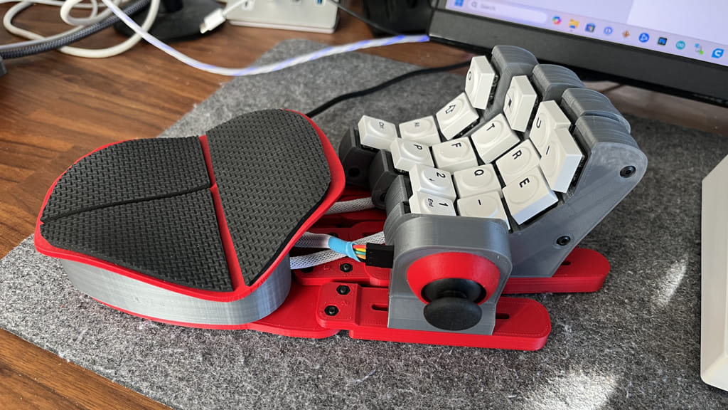
The Palm Pad — a DIY gaming keypad with a joystick
This post will walk you through the process of building a DIY gaming pad that includes a joystick, which I’m calling the Palm Pad. The post is long, but if you’re interested in all of the details of how you can make one for yourself, you’re in the right place.
Table of Contents
- Inspiration
- Instructable Build Results
- Revision Summary
- Preparing for the Build
- Parts List
- 3D Printed Parts
- The Build Process
- Install the Teensy Software
- Configure the Keybinds
- Final Thoughts
Inspiration
When Path of Exile 2’s The Third Edict came out at the end of August in 2025, I decided that I was going to start out as a Mercenary. The big thing about this class, along with the ranger, is that it reportedly plays well with WASD movement control. So I was all about that.
After a few days of play, I was liking WASD, but found that when I was in intense fights, it was difficult to keep moving and use the same fingers to press the action keys. To press my health potion, I needed to take my fingers off of the WASD if I was running away. This got me searching for a keypad that had a joystick integrated.
After some searches, I found there were a few commercial keypads with joysticks for movement. Razer had the Tartatus, Logitech has the G13, and Azeron has the Cyborg.
While all of these looked interesting, they cost more than I wanted to spend. The one thing that was different about the Azeron was that it looked like some, if not all, of it’s parts were 3D printed, and this fact sent me back to google with a new search for “DIY 3D Printed Gamepads”.
And that’s when I saw this instructable.
After seeing this I knew it could be made, and I was up for the task. This is how it all started.
Attribution & Fair Use
Azeron, Razer, and Logitech and any brands mentioned are trademarks of their owner. This project is an independent, non-commercial build inspired by the concept. Files and instructions are provided for personal, educational use only.
Instructable Build Results
After gathering up all the items needed to make the gamepad from the instructable, I printed it out and started to get it put together. The one thing I immediately noticed was that it wasn’t very comfortable. This was mostly due to the shape of the palm rest, but there were other issues as well.
In reviewing the instructable, I noticed that the author mentioned that they had created a discord for people to share info and notes. I was really impressed by some of the creative mods that people had come up with in the discord, and also stumbled on a different set of 3d files for a different gamepad that looked more like the Azeron.
Link to the Instructable author’s Discord Server
I downloaded the model I found there and started printing it out. This model was better, but it had more buttons than I needed. I saw some mods that others in the discord had made so I went ahead and made some of my own. Below are the details of the different changes that I made.
Revision Summary
Version 0
This was the original build based 100% percent off the instructable files. I wasn’t happy with this one so I didn’t take pictures or keep it around.
Version 1


- Changed the towers to remove top buttons
- Changed the model to get rid of any heat press inserts - used self tapping M3 screws or nuts instead
- Changed the electronics box to fit the teensy 4.0
- Changed the electronics box to use a custom micro-usb to usb-c extension
- Made my own thumbstick enclosure
- Modified the fingers/thumb tower mounts
This used mostly all of the files from the Azeron style replica that I found on Discord. Everything was working, but I couldn’t deal with the learning curve of the paddles without key lettering.
Version 2


- Updated towers to use Cherry MX style buttons
- Used hot-swap switch connectors
- Replaced the self tapping tower connectors with M3 nuts and screws
- Changed the angle of the thumbstick enclosure so it was pointing down
After using this for a week or so, I was pretty happy with this version. The most annoying part was the palm rest. The angles of all of the “bumps” were too aggressive and I felt that if I could change the angle, it would be so much better. I researched how to do this without the original model, and found a way with Blender using their lattice tool. This lowered the angles, but the mesh of the model was a mess. I got some help from a friend who’s a blender wizard to smooth out the morphed model. I can’t believe how good it came out!

Version 3


- New Flattened Palm Rest
- Changed electronics box to fit new palm rest
- modified electronics box and base so that the teensy and palm rest are mounted to the base instead of the e-box. The e-box could be more easily swapped out if it needed to be changed for a future palm rest update.
- Swapped joysticks to a Nintendo joycon style stick
- Made a new thumbstick enclosure for a joycon.
- Modified the base with new indents for the finger screws on the bottom of the base, so that button head screws worked well.
- Lowered the towers
- Decreased the spacing of the switches on the towers to account for the new low profile switches
- Added the Azeron palm grip
Version 3 is working really well. The palm rest is so much better, but there still are a few issues that I had to address.
Version 4 - Current / Final (for now)


- Moved back to the “normal” Arduino style joystick breakout. The joycon was ok, but it was too slippery. I was having to work too hard to keep my thumb on it. I actually bought a nub extender, but that was $10 and the other stick from v2 felt better, so I went back to that.
- Changed the position of the Teensy and placed a hole in the side of the e-box to allow a normal USB-Micro cable to be used. I didn’t want to rely on the specialty usb-c extension.
- Added an additional screw to the towers near the bottom. I noticed it spreading apart when too much force was used when connecting to the fingers.
- Changed to using off the shelf no-slip grip on the palm rest. I’ll link in the parts list below.
- Modified all parts so the different screw lengths would be minimized.
This very well could be the final version. The only thing that I’ve noticed is that I’ve found myself wanting to angle the fingers at the far right of their adjustment zone. I might make a new base that allows for more of an angle of the fingers.
Version 4b - Update


I didn’t like how the USB cable coming out of the side was not really removable. If I wanted to move it off my desk,, the whole cable went with it. So I made a new e-box that had a cut out for a USB-C BreakOut. It’s a bit more soldering and you’ll need some extra parts, but I prefer being able to disconnect it from the cable. I could have tried to move the teeny right to the edge, but I was afraid it was too close to the front for all of the wires from the towers.
I’ll include the STL for this variation in the files. Make sure you choose the correct one - it’s the Type B one.
Preparing for the Build
IMPORTANT WARNING AND DISCLAIMER
There is a possibility that after completing all of the steps in this guide that your palm pad might NOT work.
There are several things that could go wrong...
- The switches are not properly soldered.
- The switches are wired differently than the sketch is expecting.
- Your Teensy is defective.
- The Teensy/Arduino Software isn’t properly installed, so you cannot upload the sketch.
- I used windows with my build, you have a mac and are hitting an issue that I didn’t encounter.
- The web based configuration tools doesn’t run on your computer/browser.
- the web based configuration tool doesn’t connect to your device.
- All of the known issues above aren’t the problem, but it still isn’t working
I don't want to discourage you from trying, in fact I think it's a fun project, but you should NOT proceed with this build if you aren't willing to risk spending the money on the parts, the time to put it all together, and then just having a funny looking brick on your desk.
If you are OK knowing the risk and you've read through the guide and think you can do all the steps, then proceed and good luck. I've tried to include all of the details in this guide that will make this successful, but don't yell at me if it isn't working at the end.
Parts List
I’m assuming that you have a 3D printer, soldering iron, and know how to solder. Your 3D printer should also be well calibrated.
For the parts below, I’m going to put the links to the things I used. for some of the items, I had them lying around, but I’ll list what I used or something similar.
- (16) - low profile MX style keyboard switches. I used these GATERON KS-33 Low Profile Banana Keyboard Switches from Amazon.
- (16) - Keycaps for the switches above. This is your choice, but I used these 7mm block profile keycaps from amazon.
- (1) - Joystick breakout. I used one from sparkfun, but I’m 95% sure that these Joystick Module for PS2 will also work.
- (1) - Teensy 4.0 microcontroller - important to get one without pins.
- (1) - 1ft of Braided Sleeving - 4mm. I now have more braided sleeving than I know what to do with because I had to by 10m. I thought about just using the ethernet cable sleeving that I removed.
- (1) - 6ft of Ethernet cable. This is probably a little more than needed. I have a bunch of old cables, so used one. you can use any wire that is around 26-28 gauge. Stranded is probably better than solid.
- (3) - 12 pin screw terminal blocks like this
- (10) - Heat Shrink wrap for ends of braided sleeving.
- (4) - Heat Shrink wrap for grounds in tower.
- Super Glue (I used the gel type)
- (9) rubber bumper feet. They should be 10mm wide. I used the 10mm x 3mm rounded ones from this pack
- (OPTIONAL) (1) - X-Protector Rubber Sheet - 4 PCS Non Slip Pads 4” x 5” for the palm rest (optional)
- (OPTIONAL) Items for e-box TYPE-B with flush USB-C
- (1) USB-C breakout
- (1) USB-Micro Male Header
- (2) M2.5 x 10mm button head hex screws and nuts. Similar item
- (4) 3” of extra wiring - you can use left over ethernet wire.
- Hardware for Towers
- (16) - M3 x 16mm button / hex head screws for main tower
- (16) - M3 nuts (5mm) for main tower
- (8) - M3 nuts (5mm) - to attach tower to finger
- (8) - M3 x 8mm button / hex head screws to attach tower to finger
- Hardware for Palm Rest
- (3) - M3 nuts (5mm) for palm rest mounts
- (3) - M3 x 16mm button / hex head screws to attach palm rest mounts to base
- Hardware for fingers
- (10) - M3 nuts (5mm) to attach fingers to base
- (10) - M3 x 8mm button / hex head screws to attach fingers to base
- Hardware for Electronics Box
- (3) - M3 nuts (5mm) - to attach e-box to base
- Hardware for Base
- (3) - M3 x 8mm button / hex head screws to base to e-box
- (1) - M3 x 10mm self-tapping button / hex screw for teensy hold down
- (2) - M3 x 10mm self-tapping button / hex screw for grounding block
- Hardware for thumbstick
- (4) - M3 x 10mm self-tapping button / hex screw for back plate
- (2) - M3 nuts (5mm) - to attach thumbstick to finger
- (2) - M3 x 8mm button / hex head screws to attach thumbstick to finger
Hardware Links
- M3 nuts (5mm)
- Total Needed: 42
- M3 x 16mm Button / Hex Head Screws
- Total Needed: 19
- M3 x 8mm Button / Hex Head Screws
- Total Needed: 23
- M3 x 10mm Self Tapping Button / Hex Head Screws
- Total Needed: 7
Estimated Cost for all items is approximately $125 US. (This doesn’t include shipping :( )
NOTE: Depending on where you get your parts, you’ll most likely get more than you need. In fact, you’ll probably get enough parts to make 2 palm pads, except for the Teensy. What I’m saying is that if you’re successful with the build - you could probably make a 2nd one for just the price of the 2nd teensy - so that’s 2 Palm Pads for $150.
Fail Fast Teensy Test
Wait - Before you buy all the parts and print everything out, you might want to start off by first just buying the teensy and running the Fail Fast Test.
I've created a simple test that you can try to run. If that works, then you should have no issues when you're done putting the palm pad together.
Here is my other post about running this test.
If this you run into issues with this test - then you can stop now and you'll only be out the cost of the teensy.
3D Printed Parts
Download the STLs from Thingiverse
All of the files can be found HERE at thingiverse.
Make sure your printer is well calibrated. The Towers have little push fit connectors that have very little room for error. You might want to print out one set of the towers and try to fit those together before you buy any of the hardware.
Generally, for all parts I used…
- A skirt for build plate adhesion
- A .4 nozzle with a .2 layer height
- Supports without a support brim.
- When used, Supports should be everywhere (not just touching build plate)
I used Cura to slice the STLs. I dumped my main Cura profile and put them with the STLs. If you’re having trouble printing, you can compare your settings to mine. I’m using cura 5.7.1
I will call out any special settings below.
The Base
- Cura: Nothing special


The Palm Rest
- Print on it’s side.
- Cura:
- Z Seam Alignment = User Specified
- Z Seam Position = Right
- Z Seam X = 300.0
- Z Seam Y = 150.0
- Seam Corner Preference = Hide Seam
- Use supports (with support brim)
- Use brim build plate adhesion (You’ll want to make sure it stays stuck to the build plate)
The goal of the seam settings is to put the seam on the bottom of the palm rest. depending on if you rotated the palm rest, pick the appropriate side.


Palm Rest Mounts
There are 2 different Palm Rest Mounts: A and B. You need (2) of the A mounts, and (1) of the B mount. The B mount is shorter and attaches to the front of the palm rest closest to the fingers. I printed these standing up, so I added a brim, but I didn’t put a brim on the supports.
- Cura:
- Use brim build plate adhesion (You’ll want to make sure it stays stuck to the build plate)
- Use supports without a brim on the support


The Towers
- Cura: Nothing special


Electro Box
- Cura: Nothing Special
- TYPE A - the hole is on the side for the usb micro cable to pass through
- TYPE B - this has the usb-c breakout mount


Fingers and Thumb
There are 3 sizes of each - use the ones that feel best for you. I have large hands and printed out a medium finger for my pinky, 3 large fingers, and a medium for the thumb.
- Cura: Nothing special


Thumbstick
There are 3 different parts of the thumbstick. You could probably print them all at once, but I printed them separately because I wanted to change the filament on the front during the print.
- Cura: For the front - I used the “Pause at Height” extension to pause the print at 12.6mm and changed the filament so the color would be different on the ring around the actual joystick nub.


Ground Block Mount, Teensy Holder, Palm Grip Cutting Guide
- Cura: Nothing special


Tower Wiring Helper
You might not need this part. It made it easier for me to keep the switches in the right place when I was figuring out where to cut the wires to the right length. But it’s IMPORTANT that you don’t connect the ground wires when using this guide. just use it to cut them to the right length.
- Cura: Nothing special

Ok. Now that everything is printed - let’s go over the build process…
The Build Process
Before we start - There’s no “right” way to do this. The order below is how I did it, but you can do it in whatever order you prefer. The only important part is how you connect the wires to the teensy.
I made a Wiring Guide so you should follow that wire ordering.
Also - some of the part colors change in the steps, that was because I took pictures while working on different revisions, and changed up the color of my filament along the way.
1. Remove All Supports
Go ahead and remove all of the supports. Everything should be pretty easy to remove. There were 2 parts that were annoying:
- The plug area of the thumbstick base.
- I had to use pliers to get all the supports out of the area where the nuts go.
- The palm rest.
- Use a knife / reaming tool or file and sanding to make the edge where the supports were nice and smooth. It’s possible.


2. Build out the Towers
2a. Prepare the wires
- Take the ethernet cable and cut it into roughly (6) x 1ft sections.
- Snip a bit of the ends, grab hold of the inner wires, and pull them out of the sheathing.
- Separate the wires into 4 pairs by colors: brown, green, blue, orange. We will use a pair per switch
- Strip off about 2-3mm from the ends of each cable - the covering will melt back some more when tinning.
- Tin the ends of each wire.
- Snip off the ends so there’s around 2-3mm of tinned cable


2b. Solder the wires to the switches
- Take your switches and tin the 2 pins on each one.
- Solder each pair of ethernet wires to the switches.
- At the end you should have 16 soldered switches. 4 of each color pair.


2c. Sink the Nuts
- Use one of the 16mm screws to pull the nuts deep into the tower side.
This is important because if you don’t the screws won’t catch into the nut when you put the 2 sides together.


2d. Connect the Grounds
- Place the switches into the tower. Important - put the towers in this order:
- 1 - Brown (closest to the electronics box)
- 2 - Green
- 3 - Blue
- 4 - Orange (farthest)
- Separate the wires on each switch.
- Take all of the white striped ones, and place them pointing down near the bottom. These will be the ground wires.
- Take all of the solid colored ones and position those going out the front hole.
- Position the switches so that there is some extra slack - the switches have about 3/4” of extra wire outside the tower.
- Cut off the excess ground wire - so there is about 2-3 inches outside the tower.
- Strip the ends of the ground wires about 1/2”
- Grab a spare white/striped wire from the cut ethernet cable. Strip the end as well around 1/2”
- Twist all of the grounds wires together. There should be 5. 4 cut from the switches, and 1 long.
- Solder the grounds together. Put some shrink wrap or electrical tape over the solder joint.
- Take the longer ground wire and position it with the other 4 solid wires pointing out the front hole.


2e. Add Shrink Wrap
- Cut a roughly 3” piece of the braided sleeve and put these 5 wires through it.
- Place the heat shrink wrap over the ends of the braided sleeving and heat that up to shrink it.


2f. Close Up the Tower
- Put the M3 2 nuts in their slot at the bottom of the tower
- Position the switches so their slightly dangling out of their holes
- Align the press fit inserts in the 2 tower sides and press them together to attach the 2 sides.
- Careful not to get any of the wires caught when press fitting together.
- Use the 16mm screws to attach the 2 sides together.


2g. Repeat the steps for towers 2-4

Take a break. You’re close to 50% done!
3. Mount the Towers to the Fingers
- Use (2) - M3 x 8mm screws through the bottom of the finger and connect with the tower.
- Use the (8) M3 nuts and (8) M3 x 8mm screws to Connect all of the fingers to the base.
- If the screws don’t reach through, try pulling the screws in like you did with the towers to sink them a little deeper into the holes in the fingers.


4. The Thumbstick
- Get all the parts of the thumbstick together.
- For my joystick breakout, the thumb wouldn’t fit, so I pulled it off and put it in the front enclosure first.
- Make a note of the pins so you know where to connect the wires to the teensy.
- Push the joystick into the front and push back in the thumb part
- Seat the front on to the joystick base. and connect with (4) M3 x 10mm Self tapping hex screws.
- Place 2 M3 nuts into the slot in the back and put the plug in front of them.
- Attach to the thumb finger.
- OK - This is where I go off script. I had some Dupont connectors, so I decided to use those instead of soldering the ethernet wire to the pins. Again, feel free to customize things as you see fit, as long as it’s wired properly, it won’t harm anything. If you just have the ethernet wires - then solder those to the pins of the thumbstick. Just make a note of which wire is the Power, Ground, Button, Vertical and Horizontal pins.
- Apply the braided sleeving like you did with the towers.
- Note - there are openings in the in the back and side of the thumbstick to account for different pin styles on your thumbstick PCB.


5. Solder the Terminal Block to the Teensy
- take the 12pin screw terminal blocks and place them on the on the Teensy.
- Make a note of the orientation and position. The Teensy will mount with it’s top side (the side with the button) on the bottom, so the Terminals need to be on the bottom.
- Make sure the openings on the screw terminals face out.
- Make sure the screw terminals are centered. We are NOT using the pins on the far ends. The teensy has 14 holes per side. We only use the center 12.
- One side of the terminal block doesn’t sit perfectly flat on the teensy because of some resistors - that’s ok. get it as close as you can.
DOUBLE CHECK EVERYTHING BEFORE SOLDERING!!!


6. Solder the Grounding Block
- Take a piece of extra ethernet wire and strip it the width of the grounding block print.
- Press the green terminal block down on the print through the holes.
- Twist the wires so they are together, and slip it through the hole on one of the sides of the print
- Get the wire as close to the pins as possible. I tried to go back and forth through them or split the wire through them. The point is to get them close so it’s easier to solder.
- Solder the wire to the pins. Try not to melt the PLA print. I don’t think it’s possible to make this solder pretty. Just make sure you hit all the pins, so they all function.
NOTE: You could test this with a multimeter if you have one. If later on, a switch isn’t working - remember it could be because the ground here wasn’t properly soldered.


7. Connecting the Towers to the Teensy & Ground
- Place the Teensy and Grounding block into the base.
- Refer to The Wiring Guide so you know which finger goes to which teensy pin
- Move the towers to the farthest position on the finger, so you’re not cutting off too much. you want to give some slack.
- I took the wires and for the ones going to the front, I cut them near the back (see pic below). DO NOT CUT THE WHITE GROUND WIRES YET.
- For the index finger which gets wired in the back, I kind of looped it around gave my self a good amount of extra. I did not want to cut too short.
- Once all of the finger switch wires are cut, then take the ground wires and move them near the grounding block and cut them so you have enough slack. These will be longer than the solid colored switch wires for all except maybe the index, since that goes into the back of the Teensy.
- Once all wires are cut to the correct length, I stripped the wires about 3mm and tinned all of them (separately). I did this so each would be one solid wire that gets placed into the screw terminals.
- Now you need to screw each wire into the screw terminal. Refer back to the The Wiring Guide to make sure you’re following the right order. I actually took out the teensy and grounding block from the base to do the wiring because that was easier for me.
- If the Teensy and grounding block weren’t screwed down to the base, do that now with the M3 x 10mm Self Tapping Screws


Ok. You’re really close now. All soldering is done, now you just need to button things up.
8. Glue the Palm Rest Mounts
- You should have 2 mounts with the letter A on them and 1 with the letter B on it.
- The 1 with the B goes in the front of the palm rest towards the fingers.
- The 2 with the A go at the back.
- NOTE - You should turn them so the opening for the nuts all face the same direction. This way the nuts won’t fall out if you hold it in one position later on.
- Put some super glue on the numbs on the bottom of the palm rest. I used the Gel Super Glue.
- press the mounts on their nubs.
- Let rest for enough time. I waited like 15 minutes.


9. Attach the Electronics Box
- attach your usb cable
- this will either be the pass-through usb-micro for e-box type A or the USB-C breakout for e-box type B.
- Seat the (3) M3 Nuts into the electronics box. Make sure the back one is pulled in very tight - because it will be under the grounding block and hard to get to.
- slide the electronics box onto the palm rest. The back should be first, so it fits under the grounding block.
- Use the (3) M3 x 8mm screws to attach the base to the electronics box.
- NOTE - If you’re having trouble with the one under the grounding block, just remove the grounding block and use 2 hands to hold it in place while you attach it to the base.


At this point you’re technically done could install the software to make sure everything is working before you screw down the palm rest. But if you’re feeling lucky, then keep going with the final steps.
10. Attach the Palm Rest
- Put the (3) M3 nuts into the palm rest mounts
- Make sure you don’t get any of the wires caught in the holes where the mounts go.
- Push the mounts down into their holes. They will be loose, so you’ll probably need to hold it together like a sandwich while you get the screws.
- Use the (3) M3 x 16mm screws to attach the palm rest to the base.

11. Put the Key Caps On
- Get your keycaps of choice and put them on the switches.


12. Cut and Apply the Palm Grip (Optional)
- Take one of the 4x5 X-Protector sheets and place the printed cutting guides on top of it.
- Make sure all of the printed guides are placed with the print-bed side down on top of the grip sheet. the little “UP” word on the parts should be visible.
- Position them so you can get the 3 cuts from the 1 sheet.
- Use an x-acto, sharp box cutter, or scissors to cut around the guides to cut out 3 pieces.
- peel off the adhesive and attach to the palm rest. The adhesive wasn’t too strong, so I was able to gently lift and reposition it one time.
NOTE - In case you’re like me and not sure about resting your palms on just any material - I reached out to the X-Protector Customer Service and asked them about the materials used in their pads and here’s what they replied with…
Our non-slip pads are made of high-quality eco-materials or a mix of natural fibers, rubber foam, and premium adhesive. The foam is safe for the skin.


13. Apply the no-slip bumper feet
- Put the bumper feet in the zones on the base and fingers

Boom! You’re all done with the build.
Now we need to install the software and configure the keybinds.
Download the Program Files from Github
All of the files can be found HERE at my Github Repository.
Install the Teensy Software
This is where it’s more difficult to provide you with the exact steps. There are several ways to go about this depending on your OS (Windows/Mac) and development preferences. I’ll describe what I’m doing and provide links to the software I’m using. If you’ve not done this before, remember Google is your friend, and there are lots of posts and videos of people setting up a Teensy.
The key points are that:
- You need an interactive development environment (IDE) to load the Palm Pad program. I use the Arduino IDE
- You need to install the Teensy Libraries and Software loader to upload (flash) the Palm Pad program onto your teensy. This loader is called Teensyduino.
- You need to install the right version of Teensyduino that matches with the IDE you are using.
My Setup
- I’m using Windows 11.
- I’m using the Arduino IDE version 1.8.19.
- If you’d like to use the same thing, you’ll need to select the Legacy IDE from their site, otherwise they’d prefer you use the newer 2.x version of their IDE. That should work too - but I prefer the 1.8.19 version.
- I’m using the latest (at this time) version of Teensyduino.
- The link is kind of hard to see on their web page, because there are a lot of other links there, but it’s down in the section that says Arduino 1.8.x Software Development (Download and Run Installer)


Steps to Upload the sketch
- The Palm Pad program (teensy sketch) can be downloaded from Github.
- Connect your Teensy to your computer with a DATA USB cable. Make sure the cable isn’t a charge only cable.
- Open the
palmpad_teensy.inosketch in Arduino - In the Tools Menu, make sure to set the
USB TypetoSerial + Keyboard + Mouse + Joystick - In the Tools Menu, make sure to select the correct
PORTfor your teensy. - Click on the
Uploadbutton in Arduino. - There are many times where you might need to press the button on your teensy to complete the upload. Look for any messages in the console of the Arduino IDE. If you see a message that you need to press the
PROGRAM MODE BUTTON- do so. - When the compilation and upload complete, you will see a message above the console that says
Done uploading.


Troubleshooting the Teensy Sketch Upload
If you’re having trouble with uploaded, try these troubleshooting steps
Configure the Keybinds
Now that you’ve got the Palm Pad sketch flashed to your Teensy, it’s time to use the web based configurator to set your keybinds and calibrate the joystick.
If you downloaded the local copy of the web configurator from github, open the index.html file in the palmpad_config/ folder.
If you want to run the online version - click here.
When the Palm Pad is connected to the web configuration tool, it will not send keypresses to your computer. If you want to test your settings, you’ll need to disconnect first.
Steps to configure your Palm Pad
- Open up the web configuration tool
- Use the local or the online version
- Connect to your
PALMPADserial device.- NOTE - if you press a button on your Palm Pad, it should light up in the configurator, so you can make sure you’re setting the correct one.
- Select the preset you want to configure from the pull - down in the top header
- Optionally - change the preset name
- Press on the tile of the button you want to re-configure
- The button edit screen will appear.
- You can set up to 3 key presses to send when you tap the button on the Palm Pad.
- To change the button, click into the field on the edit popup, then press the key you want it to be on the keyboard.
- Note - I’ve not tested this on all keyboards, so let me know in the Github issues if the key you’re pressing doesn’t register.
- Press on the Edit button in the Thumbstick panel to change some joystick settings.
- On thing that you might want to change is the mode.
- ARPG will combine the WASD keypress so that you move diagonally
- FPS will move normally. Note: I’ve never actually tested this :)
- On thing that you might want to change is the mode.
- Press on the Calibrate button to calibrate your thumbstick.
- THIS IS SO IMPORTANT TO DO
- After pressing the calibrate button, move your joystick around to the full extents.
- The calibration will only take a few seconds.
- Note - you will need to do this for each preset.
- I might change this to be global in a future update.
- Set the button press on the thumbstick by pressing the panel under the calibration zone.


Notes on the Web Configuration Tool
- You need to calibrate the joystick for each preset (sorry).
- The settings are saved after you change them. There is no global “Save” button.
- When connected to the web configuration tool, the Palm Pad doesn’t send keypress to your computer. Disconnect to test
- If you want to completely wipe and start over - there is a way, it’s just not documented.
- Go into the Teensy code and add
factoryResetAllPresets();to the bottom of yoursetup()function. - Flash once with that in there, then remove it that line and flash it again with it removed.
- Let me know in the Github issues if you think this should be added to the web configuration tool.
- Go into the Teensy code and add
- I’ve only used the ARPG mode. In theory FPS should work properly :)
Final Thoughts
I’ve had a lot of fun working on this project. Big thanks to everyone in the Discord who shared their projects, it’s one of the big reasons I decided to write up this guide detailing my mods and sharing my code.
I’ve tried my best to document everything so you’d be successful, but I might have left something out, gotten the order wrong, or forgotten something that caused you grief. Sorry if I did, and let me know in one of the platforms that allows comments (Discord, Github issues, Thingiverse).
If you successfully make this project and are having great fun with it - let me know! Share the project and, if you are able, you can buy me a coffee with the link below.

Thanks and Enjoy!!